My RS485 BUS hardware build...

For everything that's not in any way related to PureBasic. General chat etc...
marc_256
Addict
Addict
Posts: 835
Joined: Thu May 06, 2010 10:16 am
Location: Belgium
Contact:

My RS485 BUS hardware build...

Post by marc_256 »

My RS485 BUS hardware build...

I gone try to build the [MASTER] and [SLAVE] in one PC.
- [MASTER] will be the PB5.73x64 / PLC program.
- [SLAVE 01] the PB5.73x64 / 3D simulation program.

Here are the results of my plan to connect all together.

As I'm building my RS485 control units myself (Teensy 3.2 / 4.0 / 4.1) programmed with Arduino IDE.
On a RS485 BUS I can control a max. of 32 different channels (addresses)

So, To speed up the communication, I can give each module a dual address:
- [Add_xx] = 1 address for individual data communication in Read/Write (Receive/Send) mode.
- [Add_30] = address for general data for more than one module only Read (Receive) Mode.
so, with one ascii command string I can control multiple units.

- My hardware BlockDiagram (see image below)


Thanks,
Marc,

Comming more ...


Image
- every professional was once an amateur - greetings from Pajottenland - Belgium -
PS: sorry for my english I speak flemish ...
User avatar
Erolcum
User
User
Posts: 51
Joined: Fri Jun 07, 2024 10:45 am
Location: Turkiye
Contact:

Re: My RS485 BUS hardware build...

Post by Erolcum »

marc_256 wrote: Fri Aug 30, 2024 1:26 pm My RS485 BUS hardware build...

I gone try to build the [MASTER] and [SLAVE] in one PC.
- [MASTER] will be the PB5.73x64 / PLC program.
- [SLAVE 01] the PB5.73x64 / 3D simulation program.
Hello Marc,

I can not understand your master. is it mini pc ? why you write PLC ? Why pc communicates itself ? (master slave in one pc)
PB5.73x64 / PLC program. did you write a plc simulation with pb ?
You may visit my new Purebasic blog here..
:arrow: https://erolcum-github-io.translate.goo ... r_pto=wapp
User avatar
Erolcum
User
User
Posts: 51
Joined: Fri Jun 07, 2024 10:45 am
Location: Turkiye
Contact:

Re: My RS485 BUS hardware build...

Post by Erolcum »

ok, I read the other topic that you mentioned about communicating programs on the same pc.. There is a program or driver we can say, it creates com1 and com2 virtually on same pc. if one program send data to com1, another program can read data sent from com2.. it is like a bridge. there is no need for a hardware.. btw, you can open a serial port with only one program at that time.
https://erolcum-blogspot-com.translate. ... r_pto=wapp
You may visit my new Purebasic blog here..
:arrow: https://erolcum-github-io.translate.goo ... r_pto=wapp
User avatar
Erolcum
User
User
Posts: 51
Joined: Fri Jun 07, 2024 10:45 am
Location: Turkiye
Contact:

Re: My RS485 BUS hardware build...

Post by Erolcum »

you can create 2 com port pairs to communicate 3 PB programs without any hardware.. Link for virtual com ports on my message above.
https://r.resimlink.com/D4OtUlzRe8Z.jpeg
You may visit my new Purebasic blog here..
:arrow: https://erolcum-github-io.translate.goo ... r_pto=wapp
tj1010
Enthusiast
Enthusiast
Posts: 716
Joined: Mon Feb 25, 2013 5:51 pm

Re: My RS485 BUS hardware build...

Post by tj1010 »

I'm assuming this is for motor controls or RF or some type of sensor logging. The PB stuff could just use IPC like named pipes or mkfifo or the more popular solution, for some reason, loop back sockets.
marc_256
Addict
Addict
Posts: 835
Joined: Thu May 06, 2010 10:16 am
Location: Belgium
Contact:

Re: My RS485 BUS hardware build...

Post by marc_256 »

Hello,


First at all I want to thank Infratec and SMaag for the software integration in PB.
see here : viewtopic.php?t=85050 8)
and here : viewtopic.php?t=85253 8)


I'm working on my hardware RS485 Converter module:

-------------------------------------------------------------------------------------------------------------------------------------
- What do I need:
-------------------------------------------------------------------------------------------------------------------------------------
1 ) - As the industry uses a power supply of 24VDC, power inputs from 12...30 VDC, Output 5VDC / 2...5Amp

2 ) - Connection with RS485 BUS.
- Programmable addresses for the RS485 BUS.

3 ) - Understand MODBUS protocol and edit/answer the commands.

4 ) - Development for multiple uses
RS485 ->
Discreet I/O
Analog I/O
Other communications - Second RS485 (use as extender/repeater)
- CAN Bus
- RS232 (serial)
- UART
- SPI
- I2C
- ... ?

5 ) - Level converter for 3.2, 5.0 or 24 (opto isolation) volt I/O uses.

6 ) - A assembling box with connections ...

7 ) - Stand alone for GERBER control of my (future) 3 axis CNC machine.

8 ) - The extensions ...


-------------------------------------------------------------------------------------------------------------------------------------
- The results till now: This are pre pre PCB prototype examples (only for positioning the parts)
-------------------------------------------------------------------------------------------------------------------------------------
1 ) POWER SUPPLY module: see Image1
- Input voltages form 5...30VDC / Currents 3.2/5.0 Amp.
- For now, not galvanic isolated (price) ... and the size is important for my assembling box.

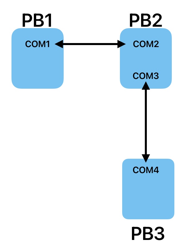
2 ) CONNECTION WITH RS485 BUS: see Image2 (bottom module) and Image5 keypad
- Can even be used as a repeater for extension to 32+ nodes.
- Addresses are programmable via little keypad and small color lcd display (240x240 px)
- LCD can be used as a small user status update viewer.


3 ) MODBUS PROTOCOL: see Image4
- Must be programmed via Teensy 3.2 or Teensy 4.0 MPU module.


4 ) MULTIPLE I/O USE: see Image2
- Via the interchangeable I/O module, I can install CAN, RS232, RS485, UART, ... converters to the Teensy 3.2 and Teensy 4.0 MPU module.
- If I want to use more modules on one BUS I need to remove the 120 Ohm resistor on the RS485 converters.


5 ) LEVEL CONVERTERS: see Image3
- Level converter from 3.3 to 5.0 volt I/O, Stepper controllers,
- Opto module for the 24 VDC I/O


6 ) THE ASSEMBLING BOX: see Image6
- I chose a small IP65 box (do not need it for now), with transparent front.
- So I can follow the status on the small LCD.


7 ) STAND ALONE: see Image4
- For the GERBER controller, the Teensy 4.0 works on a 600MHz clock and have 32 and 64 bits hardware floating point on board.
- To execute circular COS, SIN, TAN controls it is much faster.
- If I use the extra audio board, I can use an SD card memory extension (not tested).


8 ) EXTENSIONS:
- ...


Love to receive some remarks ...
Greetings
Marc,


Image


Image


Image


Image


Image


Image
- every professional was once an amateur - greetings from Pajottenland - Belgium -
PS: sorry for my english I speak flemish ...
Post Reply