However, I need to import line drawings whose points are defined in a typical CAD coordinate system:
How do I move and 'flip' the default system to work as above, with the points of each line being absolute?

Code: Select all
If OpenWindow(0, 0, 0, 450, 300, "VectorDrawing", #PB_Window_SystemMenu | #PB_Window_ScreenCentered)
CanvasGadget(0, 0, 0, 450, 300)
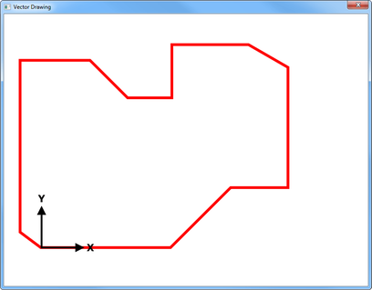
If StartVectorDrawing(CanvasVectorOutput(0))
AddPathSegments("M 40 20 L 120 20 L 120 60 L 200 60 L 200 100 L 280 100 L 280 140 L 360 140 L 360 180")
VectorSourceColor(RGBA(255, 0, 0, 255))
StrokePath(5, #PB_Path_RoundCorner)
TranslateCoordinates(30, 30)
AddPathSegments("M 40 20 L 120 20 L 120 60 L 200 60 L 200 100 L 280 100 L 280 140 L 360 140 L 360 180")
VectorSourceColor(RGBA(0, 0, 255, 255))
StrokePath(5, #PB_Path_RoundCorner)
StopVectorDrawing()
EndIf
Repeat
Event = WaitWindowEvent()
Until Event = #PB_Event_CloseWindow
EndIf
Code: Select all
New_Y = PB_Y - DXF_YYes, but on this side, this should not be a problem, because in most CAD programs (using the metric system) we work in "drawing units" (dots)infratec wrote:And it is possible that the coordinates from the CAD file are in mm or something else, normaly not in pixel.
So you have to transform them.
Do not invert the Y values (you would get a mirror, so the text (cotations) would be unusable)IdeasVacuum wrote: Yeah - I was hopeful about the coordinate system but if that's a no, I shall invert all the Y values on import.
Code: Select all
; SVG to PB Vector Drawing

; How exported CAO look like (in SVG)
; Rectangular triangle exported in SVG by GCAD
; 90° angle at bottom left (at 0.0)
; |\
; | \
; +--  I'm poor in ascii art :'(
;
; <?xml version="1.0" encoding="UTF-8"?>
; <!-- 2019-11-08 14:51:23 Generated by QCAD SVG Exporter -->
; <svg width="30" height="30" viewBox="0 -30 30 30" version="1.1" xmlns="http://www.w3.org/2000/svg" style="stroke-linecap:round;stroke-linejoin:round;fill:none">
;     <g transform="scale(1,-1)">
;         <!-- Ligne -->
;         <path d="M0,0 L30,0 " style="stroke:#000000;stroke-width:0.25;"/>
;         <!-- Ligne -->
;         <path d="M30,0 L0,30 " style="stroke:#000000;stroke-width:0.25;"/>
;         <!-- Ligne -->
;         <path d="M0,30 L0,0 " style="stroke:#000000;stroke-width:0.25;"/>
;     </g>
; </svg>

; SVG: x, y
;  0,0  to 30,0
; 30,0  to  0,30
;  0,30 to  0,0

EnableExplicit

Structure Type_Line
    X_From.i
    Y_From.i
    X_To.i
    Y_To.i
EndStructure
NewList Line_XY.Type_Line()

Restore Draw:

Define i
For i = 1 To 3
    AddElement(Line_XY())
    With Line_XY()
        Read.i \X_From
        Read.i \Y_From
        Read.i \X_To
        Read.i \Y_To
    EndWith
Next

OpenWindow(0, 0, 0, 540, 540, "CAD 2 PB Vector", #PB_Window_SystemMenu | #PB_Window_ScreenCentered)
CanvasGadget(0, 10, 10, 520, 520)

If StartVectorDrawing(CanvasVectorOutput(0))
    TranslateCoordinates(10, 10)
    FirstElement(Line_XY())
    ; Origine PB
    ForEach Line_XY()
        With Line_XY()
            MovePathCursor(\X_From, \Y_From)
            AddPathLine(\X_To, \Y_To)
        EndWith
    Next
    VectorSourceColor(RGBA(0, 0, 255, 255))
    StrokePath(3)

    ; Corrected
    Define New_Y = 500
    FirstElement(Line_XY())
    ForEach Line_XY()
        With Line_XY()
            MovePathCursor(\X_From, New_Y - \Y_From)
            AddPathLine(\X_To, New_Y - \Y_To)
        EndWith
    Next
    VectorSourceColor(RGBA(255, 0, 0, 255))
    StrokePath(3)

    StopVectorDrawing()
EndIf

Repeat
    Define Event = WaitWindowEvent()
Until Event = #PB_Event_CloseWindow

End

DataSection
    Draw:
    Data.i  0,    0, 300, 0
    Data.i 300,   0,   0, 300
    Data.i  0,  300,   0, 0
EndDataSection

This is a BIG no no if you are dealing with accuracy and object intersections. You must use integer math and/or scale your drawing units way above the limited pixels within the viewable area.IdeasVacuum wrote:The Vector Lib does allow different units, including mm. For the purposes of displaying the shape and it's vicinity to other shapes, pixels are fine.
Code: Select all
;-TOP
; Flip Y-Coordinates by mk-soft, v0.6

EnableExplicit

Global _IsFlipped_, _OldY_.d

Macro _PB_(Function)
  Function
EndMacro

Macro BeginFlipCoordinates()
  FlipCoordinatesY(VectorOutputHeight() * 0.5) : _IsFlipped_ = #True
EndMacro

Macro EndFlipCoordinates()
  _PB_(ResetCoordinates)() : _IsFlipped_ = #False
EndMacro

Macro ResetCoordinates(_Value_=#PB_Coordinate_User)
  _PB_(ResetCoordinates)(_Value_) : If _IsFlipped_ : FlipCoordinatesY(VectorOutputHeight() * 0.5, _Value_) : EndIf
EndMacro

Macro DrawVectorText(_Text_)
  If _IsFlipped_
    _OldY_ = PathCursorY()
    FlipCoordinatesY(_OldY_) : _PB_(DrawVectorText)(_Text_) : FlipCoordinatesY(_OldY_)
  Else
    _PB_(DrawVectorText)(_Text_)
  EndIf
EndMacro

Define i

If OpenWindow(0, 0, 0, 450, 300, "VectorDrawing", #PB_Window_SystemMenu | #PB_Window_ScreenCentered)
  CanvasGadget(0, 0, 0, 450, 300)
  LoadFont(0, "Impact", 11)

  If StartVectorDrawing(CanvasVectorOutput(0))
    VectorFont(FontID(0))

    MovePathCursor(10, 10)
    DrawVectorText("Flip Coordinates Example")

    BeginFlipCoordinates()

    ; Part 1
    ResetCoordinates()

    AddPathSegments("M 40 20 L 120 20 L 120 60 L 200 60 L 200 100 L 280 100 L 280 140 L 360 140 L 360 180")
    VectorSourceColor(RGBA(255, 0, 0, 255))
    StrokePath(5, #PB_Path_RoundCorner)

    MovePathCursor(10, 30)
    RotateCoordinates(10, 30, 45)
    DrawVectorText("Red Line")

    ;Part 2
    ResetCoordinates()

    TranslateCoordinates(50, 50)

    AddPathSegments("M 40 20 L 120 20 L 120 60 L 200 60 L 200 100 L 280 100 L 280 140 L 360 140 L 360 180")
    VectorSourceColor(RGBA(0, 0, 255, 255))
    StrokePath(5, #PB_Path_RoundCorner)

    MovePathCursor(10, 30)
    RotateCoordinates(10, 30, 45)
    DrawVectorText("Blue Line")

    ; Part 3
    ResetCoordinates()

    AddPathCircle(80, 80, 50, 0, 45)
    VectorSourceColor(RGBA(255, 0, 0, 255))
    StrokePath(5, #PB_Path_RoundCorner)

    AddPathCircle(80, 80, 50, 45, 90)
    VectorSourceColor(RGBA(0, 0, 255, 255))
    StrokePath(5, #PB_Path_RoundCorner)

    ; Part 4
    ResetCoordinates()

    VectorSourceColor(RGBA(64, 64, 64, 255))
    For i = 0 To 260 Step 20
      MovePathCursor(420, i + 20)
      DrawVectorText(Str(i))
    Next

    EndFlipCoordinates()

    StopVectorDrawing()
  EndIf

  Repeat
    Define Event = WaitWindowEvent()
  Until Event = #PB_Event_CloseWindow
EndIf
Code: Select all
Procedure lline(x1,y1,x2,y2)
  ResetCoordinates()
  FlipCoordinatesY(90)
  MovePathCursor(x1,y1)
  AddPathLine(x2,y2)
EndProcedure

  If OpenWindow(0, 0, 0, 800, 200, "VectorDrawing", #PB_Window_SystemMenu | #PB_Window_ScreenCentered)
    CanvasGadget(0, 0, 0, 800, 200)
    ;Line01 Pt01 101.1176, 0.0000 Pt02 756.6081, 0.0000
    ;Line02 Pt01 739.8827, 106.6284 Pt02 10.0000, 167.9937
    ;Line03 Pt01 10.0000, 167.9937 Pt02 101.1176, 0.0000
    ;Line04 Pt01 739.8827, 106.6284 Pt02 756.6081, 0.0000
    If StartVectorDrawing(CanvasVectorOutput(0))
      lline(101,0,756,0)
      lline(739,106,10,167)
      lline(10,167,101,0)
      lline(739,106,756,0)
      VectorSourceColor(RGBA(255, 0, 0, 255))
      StrokePath(1)

      StopVectorDrawing()
    EndIf

    Repeat
      Event = WaitWindowEvent()
    Until Event = #PB_Event_CloseWindow
  EndIf
Code: Select all
; Drawing from CAD file

EnableExplicit

Enumeration
    #hFile
    #Win
    #Canvas
EndEnumeration

Structure Type_Line
    x1.l
    y1.l
    x2.l
    y2.l
EndStructure
NewList vLine.Type_Line()

Define Data_File$ = "Datas.txt" ; (see content sample below)

; Line01 Pt01 101.1176, 0.0000 Pt02 756.6081, 0.0000
; Line02 Pt01 739.8827, 106.6284 Pt02 10.0000, 167.9937
; Line03 Pt01 10.0000, 167.9937 Pt02 101.1176, 0.0000
; Line04 Pt01 739.8827, 106.6284 Pt02 756.6081, 0.0000

OpenWindow(#Win, 0, 0, 800, 300, "", #PB_Window_SystemMenu | #PB_Window_ScreenCentered)
CanvasGadget(#Canvas, 10, 10, WindowWidth(#Win) - 20, WindowHeight(#Win) - 20)
Define New_Y = GadgetHeight(#Canvas)

; --- Load datas from file
If Not OpenFile(#hFile, Data_File$)
    Debug "Can't Load Datas"
    End
EndIf
Debug "Reading..."
While Not Eof(#hFile)
    AddElement(vLine())
    Define Tmp_Line$ = ReadString(#hFile)
    With vLine()
        \x1 =         Val(StringField(Tmp_Line$, 3, " "))
        \y1 = New_Y - Val(StringField(Tmp_Line$, 4, " "))
        \x2 =         Val(StringField(Tmp_Line$, 6, " "))
        \y2 = New_Y - Val(StringField(Tmp_Line$, 7, " "))
    EndWith
Wend
Debug "Read Done."
CloseFile(#hFile)

If StartVectorDrawing(CanvasVectorOutput(#Canvas))
    With vLine()
        ForEach vLine()
            MovePathCursor(\x1, \y1)
            AddPathLine   (\x2, \y2)
        Next
    EndWith
    VectorSourceColor(RGBA(0, 0, 255, 255))
    StrokePath(1)
    StopVectorDrawing()
EndIf

Repeat : Until WaitWindowEvent() = #PB_Event_CloseWindowCode: Select all
Line01 Pt01 101.1176, 0.0000 Pt02 756.6081, 0.0000
Line02 Pt01 739.8827, 106.6284 Pt02 10.0000, 167.9937
Line03 Pt01 10.0000, 167.9937 Pt02 101.1176, 0.0000
Line04 Pt01 739.8827, 106.6284 Pt02 756.6081, 0.0000


