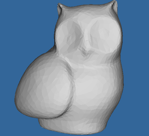
So far I have been testing with glMaterialfv() plus a light (or two) but with no success.
I think I need a Shader to achieve this, but how?
Below is a screenshot from a CAD program that gets it right:
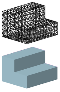

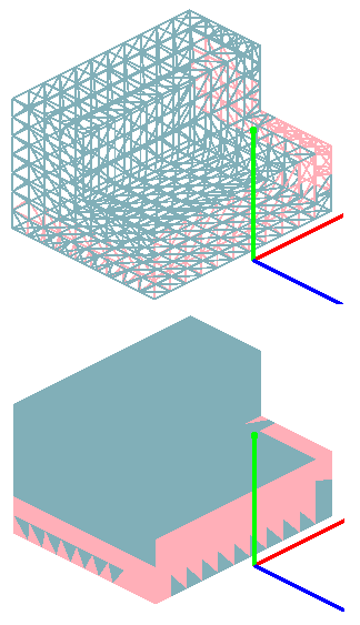
I was unsure about that, some online OpenGL tutorials contravening others. So currently, my code has one normal per triangle face, as per the STL itself. I'll change it. The normal directions do check out correctly for the sample mesh.Does every vertex have a normal assigned to it?
Code: Select all
facet normal 0.468282 -0.863498 -0.187306
Code: Select all
glPolygonMode_(#GL_FRONT_AND_BACK, #GL_FILL )Code: Select all
Global Dim LightPos.f(4) ;Light Position
 LightPos(0)= 0.0 : LightPos(1)= 15.0 : LightPos(2)=-40.0 : LightPos(3)= 10.0
Global Dim LightAmb.f(4) ;Ambient Light Values
 LightAmb(0)= 0.2 : LightAmb(1)= 0.2 : LightAmb(2)= 0.2 : LightAmb(3)= 1.0
Global Dim LightDif.f(4) ;Diffuse Light Values
 LightDif(0)= 0.6 : LightDif(1)= 0.6 : LightDif(2)= 0.6 : LightDif(3)= 1.0
Global Dim LightSpc.f(4) ;Specular Light Values
LightSpc(0)=-0.2 : LightSpc(1)=-0.2 : LightSpc(2)=-0.2 : LightSpc(3)= 1.0

Global Dim MatAmb.f(4) ;Material - Ambient Values
 MatAmb(0)= 0.4 : MatAmb(1)= 0.4 : MatAmb(2)= 0.4 : MatAmb(3)= 1.0
Global Dim MatDif.f(4) ;Material - Diffuse Values
 MatDif(0)= 1.2 : MatDif(1)= 0.6 : MatDif(2)= 0.0 : MatDif(3)= 1.0
Global Dim MatSpc.f(4) ;Material - Specular Values
 MatSpc(0)= 0.0 : MatSpc(1)= 0.0 : MatSpc(2)= 0.0 : MatSpc(3)= 1.0
Global Dim MatShn.f(1) ;Material - Shininess
MatShn(0)= 0.0


glClearColor_ (0.0, 0.0, 0.0, 0.0);
glShadeModel_ (#GL_SMOOTH)

glEnable_(#GL_LIGHTING);
glEnable_(#GL_LIGHT0);
glEnable_(#GL_DEPTH_TEST);

glLightfv_(#GL_LIGHT1,#GL_POSITION,LightPos()) ;Set Light1 Position
glLightfv_(#GL_LIGHT1,#GL_AMBIENT,LightAmb()) ;Set Light1 Ambience
glLightfv_(#GL_LIGHT1,#GL_DIFFUSE,LightDif()) ;Set Light1 Diffuse
glLightfv_(#GL_LIGHT1,#GL_SPECULAR,LightSpc()) ;Set Light1 Specular
glEnable_(#GL_LIGHT1) ;Enable Light1
glEnable_(#GL_LIGHTING) ;Enable Lighting

glMaterialfv_(#GL_FRONT,#GL_AMBIENT,MatAmb()) ;Set Material Ambience
glMaterialfv_(#GL_FRONT,#GL_DIFFUSE,MatDif()) ;Set Material Diffuse
glMaterialfv_(#GL_FRONT,#GL_SPECULAR,MatSpc()) ;Set Material Specular
glMaterialfv_(#GL_FRONT,#GL_SHININESS,MatShn());Set Material Shininess
Code: Select all
EnableExplicit

;-STRUCTURES
Structure Long3
  X.l
  Y.l
  Z.l
EndStructure

Structure Vector3
  X.f
  Y.f
  Z.f
EndStructure

Structure ObjectData
  Handle.b
  VertexCTR.l
  VertexLimit.l
  Array Vertex.Vector3(0)
  Array Normal.Vector3(0)
  TriangleCTR.l
  TriangleLimit.l
  Array Triangle.Long3(0)
EndStructure

;-DECLARES
Declare ImportStl(Path.s)
Declare Render()
Declare SetupGL()

Declare MATH_Normalize3D(*Value.Vector3)
Declare MATH_TriangleNormal(*V1.Vector3, *V2.Vector3, *V3.Vector3, *Result.Vector3)

;-DEFINES AND GLOBALS
Define.l Event
Define.l Quit

Global.ObjectData Object

Global.f RollAxisX
Global.f RollAxisY
Global.f RollAxisZ

Global.f RotateSpeedX = 0.0
Global.f RotateSpeedY = 1.0
Global.f RotateSpeedZ = 1.0

Global.f ZoomFactor = -10.0 ;Decrease value to zoom out.

;-MAIN WINDOW
OpenWindow(0, 0, 0, 800, 600, "Stl file import", #PB_Window_SystemMenu | #PB_Window_ScreenCentered)

OpenGLGadget(0, 0, 0, 800, 600)
SetupGL()

If ImportStl("Test.stl") = #False
  MessageRequester("Error", "Failed to import object.")
  End
EndIf

;-MAIN REPEAT
Repeat

  Repeat
    Event = WindowEvent()

    If Event = #PB_Event_CloseWindow
      Quit = 1
    EndIf
  Until Event = 0

  Render()

Until Quit = 1
End

;-
;-PROCEDURES
Procedure ImportStl(Path.s)

  Define.l Epos
  Define.l File
  Define.l Spos

  Define.s Result
  Define.s String

  Define.Vector3 Normal

  ;Make sure file exists.
  File = ReadFile(#PB_Any, Path)
  If IsFile(File) = 0
    ProcedureReturn #False
  EndIf

  ;Begin File Reading
  With Object
    \Handle = 1

    While Eof(File) = 0
      Result = ReadString(File, #PB_Ascii)

      ;Find triangles
      If Mid(Result, 0, 5) = "facet"
        ;Collect triangle's data
        While Eof(File) = 0
          Result = ReadString(File, #PB_Ascii)

          If Mid(Result, 0, 6) = "vertex"
            ;Found vertex data
            If \VertexCTR + 1 >= \VertexLimit
              \VertexLimit + 1000
              ReDim \Vertex(\VertexLimit)
              ReDim \Normal(\VertexLimit)
            EndIf

            \VertexCTR + 1

            Spos = 8
            Epos = FindString(Result, " ", Spos)
            String = Mid(Result, Spos, Epos-Spos)
            \Vertex(\VertexCTR)\X = ValF(String)
            Spos = Epos + 1

            Epos = FindString(Result, " ", Spos)
            String = Mid(Result, Spos, Epos-Spos)
            \Vertex(\VertexCTR)\Y = ValF(String)
            Spos = Epos + 1

            Epos = FindString(Result, " ", Spos)
            String = Mid(Result, Spos)
            \Vertex(\VertexCTR)\Z = ValF(String)
          EndIf

          ;Found end of triangle
          If Mid(Result, 0, 8) = "endfacet"
            ;Store Triangle data
            If \TriangleCTR + 1 >= \TriangleLimit
              \TriangleLimit + 1000
              ReDim \Triangle(\TriangleLimit)
            EndIf

            \TriangleCTR + 1

            \Triangle(\TriangleCTR)\X = \VertexCTR-2
            \Triangle(\TriangleCTR)\Y = \VertexCTR-1
            \Triangle(\TriangleCTR)\Z = \VertexCTR

            ;Calculate triangle's normal
            MATH_TriangleNormal(@\Vertex(\VertexCTR-2), @\Vertex(\VertexCTR-1), @\Vertex(\VertexCTR), @Normal)
            \Normal(\VertexCTR-2)\X = Normal\X
            \Normal(\VertexCTR-2)\Y = Normal\Y
            \Normal(\VertexCTR-2)\Z = Normal\Z

            \Normal(\VertexCTR-1)\X = Normal\X
            \Normal(\VertexCTR-1)\Y = Normal\Y
            \Normal(\VertexCTR-1)\Z = Normal\Z

            \Normal(\VertexCTR)\X   = Normal\X
            \Normal(\VertexCTR)\Y   = Normal\Y
            \Normal(\VertexCTR)\Z   = Normal\Z

            Break
          EndIf
        Wend

        Continue
      EndIf
    Wend
  EndWith

  ProcedureReturn #True

EndProcedure

Procedure Render()

  Define.l TriCTR
  Define.l VCTR1, VCTR2, VCTR3

  Define.Vector3 Nor1, Nor2, Nor3
  Define.Vector3 Vec1, Vec2, Vec3

  SetGadgetAttribute(0, #PB_OpenGL_SetContext, #True)

  glPushMatrix_()                  ; Save the original Matrix coordinates
  glMatrixMode_(#GL_MODELVIEW)

  glTranslatef_(0, 0, ZoomFactor)  ;  move the camera out

  glRotatef_(RollAxisX, 1.0, 0, 0) ; rotate around X axis
  glRotatef_(RollAxisY, 0, 1.0, 0) ; rotate around Y axis
  glRotatef_(RollAxisZ, 0, 0, 1.0) ; rotate around Z axis

  RollAxisX + RotateSpeedX
  RollAxisY + RotateSpeedY
  RollAxisZ + RotateSpeedZ

  ; clear color and depth buffers
  glClearColor_(0.2, 0.4, 0.6, 1.0)
  glClear_(#GL_COLOR_BUFFER_BIT | #GL_DEPTH_BUFFER_BIT)

  With Object
    If \Handle = 1
      glEnable_(#GL_LIGHTING)
      glEnable_(#GL_LIGHT0)
      glBegin_(#GL_TRIANGLES)

      For TriCTR = 1 To \TriangleCTR
        VCTR1 = \Triangle(TriCTR)\X
        VCTR2 = \Triangle(TriCTR)\Y
        VCTR3 = \Triangle(TriCTR)\Z

        Vec1\X = \Vertex(VCTR1)\X
        Vec1\Y = \Vertex(VCTR1)\Y
        Vec1\Z = \Vertex(VCTR1)\Z
        Nor1\X = \Normal(VCTR1)\X
        Nor1\Y = \Normal(VCTR1)\Y
        Nor1\Z = \Normal(VCTR1)\Z

        Vec2\X = \Vertex(VCTR2)\X
        Vec2\Y = \Vertex(VCTR2)\Y
        Vec2\Z = \Vertex(VCTR2)\Z
        Nor2\X = \Normal(VCTR2)\X
        Nor2\Y = \Normal(VCTR2)\Y
        Nor2\Z = \Normal(VCTR2)\Z

        Vec3\X = \Vertex(VCTR3)\X
        Vec3\Y = \Vertex(VCTR3)\Y
        Vec3\Z = \Vertex(VCTR3)\Z
        Nor3\X = \Normal(VCTR3)\X
        Nor3\Y = \Normal(VCTR3)\Y
        Nor3\Z = \Normal(VCTR3)\Z

        glNormal3f_(Nor1\X, Nor1\Y, Nor1\Z)
        glVertex3f_(Vec1\X, Vec1\Y, Vec1\Z)

        glNormal3f_(Nor2\X, Nor2\Y, Nor2\Z)
        glVertex3f_(Vec2\X, Vec2\Y, Vec2\Z)

        glNormal3f_(Nor3\X, Nor3\Y, Nor3\Z)
        glVertex3f_(Vec3\X, Vec3\Y, Vec3\Z)
      Next
      glEnd_()
    EndIf
  EndWith

  glPopMatrix_()
  glFinish_()

  SetGadgetAttribute(0, #PB_OpenGL_FlipBuffers, #True)

EndProcedure

Procedure SetupGL()

  glMatrixMode_(#GL_PROJECTION)
  gluPerspective_(30.0, 800/600, 1.0, 1000.0)

  ; position viewer
  glMatrixMode_(#GL_MODELVIEW)

  glTranslatef_(0, 0, -5.0)

  glEnable_(#GL_DEPTH_TEST)

  glEnable_(#GL_CULL_FACE)

  glShadeModel_(#GL_SMOOTH)

EndProcedure

;-
;-MATH PROCEDURES
Procedure MATH_Normalize3D(*Value.Vector3)

  Define.d Length

  Length = Sqr(*Value\X * *Value\X + *Value\Y * *Value\Y + *Value\Z * *Value\Z)
  If Length = 0
    Length = 1
  EndIf

  *Value\X = *Value\X / Length
  *Value\Y = *Value\Y / Length
  *Value\Z = *Value\Z / Length

EndProcedure

Procedure MATH_TriangleNormal(*V1.Vector3, *V2.Vector3, *V3.Vector3, *Result.Vector3)

  *Result\X = (*V1\Y - *V2\Y) * (*V2\Z - *V3\Z) - (*V1\Z - *V2\Z) * (*V2\Y - *V3\Y)
  *Result\Y = (*V1\Z - *V2\Z) * (*V2\X - *V3\X) - (*V1\X - *V2\X) * (*V2\Z - *V3\Z)
  *Result\Z = (*V1\X - *V2\X) * (*V2\Y - *V3\Y) - (*V1\Y - *V2\Y) * (*V2\X - *V3\X)

  MATH_Normalize3D(*Result)

EndProcedure
Code: Select all
EnableExplicit
;-STRUCTURES
Structure Long3
  X.l
  Y.l
  Z.l
EndStructure

Structure Vector3
  X.f
  Y.f
  Z.f
EndStructure

Structure ObjectData
  Handle.b
  VertexCTR.l
  VertexLimit.l
  Array Vertex.Vector3(0)
  Array Normal.Vector3(0)
  TriangleCTR.l
  TriangleLimit.l
  Array Triangle.Long3(0)
EndStructure

;-DECLARES
Declare ImportStl(Path.s)
Declare Render()
Declare SetupGL()

Declare MATH_Normalize3D(*Value.Vector3)
Declare MATH_TriangleNormal(*V1.Vector3, *V2.Vector3, *V3.Vector3, *Result.Vector3)

;-DEFINES AND GLOBALS
Define.l Event
Define.l Quit

Global.ObjectData Object

Global.f RollAxisX
Global.f RollAxisY
Global.f RollAxisZ

Global.f RotateSpeedX = 0.0
Global.f RotateSpeedY = 1.0
Global.f RotateSpeedZ = 1.0

Global.f ZoomFactor = -1000.0 ;Decrease value to zoom out.

;-MAIN WINDOW
OpenWindow(0, 0, 0, 800, 600, "Stl file import", #PB_Window_SystemMenu | #PB_Window_ScreenCentered)

OpenGLGadget(0, 0, 0, 800, 600)
SetupGL()

If ImportStl("SampleMeshAscii.stl") = #False
  MessageRequester("Error", "Failed to import object.")
  End
EndIf

;-MAIN REPEAT
Repeat

  Repeat
    Event = WindowEvent()

    If Event = #PB_Event_CloseWindow
      Quit = 1
    EndIf
  Until Event = 0

  Render()

Until Quit = 1
End

;-
;-PROCEDURES
Procedure ImportStl(Path.s)

  Define.l Epos
  Define.l File
  Define.l Spos

  Define.s Result
  Define.s String

  Define.Vector3 Normal

  ;Make sure file exists.
  File = ReadFile(#PB_Any, Path)
  If IsFile(File) = 0
    ProcedureReturn #False
  EndIf

  ;Begin File Reading
  With Object
    \Handle = 1

    While Eof(File) = 0
      Result = LTrim(ReadString(File, #PB_Ascii))

      ;Find triangles
      If Mid(Result, 0, 5) = "facet"
        ;Collect triangle's data
        While Eof(File) = 0
          Result = LTrim(ReadString(File, #PB_Ascii))

          If Mid(Result, 0, 6) = "vertex"
            ;Found vertex data
            If \VertexCTR + 1 >= \VertexLimit
              \VertexLimit + 1000
              ReDim \Vertex(\VertexLimit)
              ReDim \Normal(\VertexLimit)
            EndIf

            \VertexCTR + 1

            Spos = 8
            Epos = FindString(Result, " ", Spos)
            String = Mid(Result, Spos, Epos-Spos)
            \Vertex(\VertexCTR)\X = ValF(String)
            Spos = Epos + 1

            Epos = FindString(Result, " ", Spos)
            String = Mid(Result, Spos, Epos-Spos)
            \Vertex(\VertexCTR)\Y = ValF(String)
            Spos = Epos + 1

            Epos = FindString(Result, " ", Spos)
            String = Mid(Result, Spos)
            \Vertex(\VertexCTR)\Z = ValF(String)
          EndIf

          ;Found end of triangle
          If Mid(Result, 0, 8) = "endfacet"
            ;Store Triangle data
            If \TriangleCTR + 1 >= \TriangleLimit
              \TriangleLimit + 1000
              ReDim \Triangle(\TriangleLimit)
            EndIf

            \TriangleCTR + 1

            \Triangle(\TriangleCTR)\X = \VertexCTR-2
            \Triangle(\TriangleCTR)\Y = \VertexCTR-1
            \Triangle(\TriangleCTR)\Z = \VertexCTR

            ;Calculate triangle's normal
            MATH_TriangleNormal(@\Vertex(\VertexCTR-2), @\Vertex(\VertexCTR-1), @\Vertex(\VertexCTR), @Normal)
            \Normal(\VertexCTR-2)\X = Normal\X
            \Normal(\VertexCTR-2)\Y = Normal\Y
            \Normal(\VertexCTR-2)\Z = Normal\Z

            \Normal(\VertexCTR-1)\X = Normal\X
            \Normal(\VertexCTR-1)\Y = Normal\Y
            \Normal(\VertexCTR-1)\Z = Normal\Z

            \Normal(\VertexCTR)\X   = Normal\X
            \Normal(\VertexCTR)\Y   = Normal\Y
            \Normal(\VertexCTR)\Z   = Normal\Z

            Break
          EndIf
        Wend

        Continue
      EndIf
    Wend
  EndWith

  Debug Object\VertexCTR
  Debug Object\TriangleCTR

  ProcedureReturn #True

EndProcedure

Procedure Render()

  Define.l TriCTR
  Define.l VCTR1, VCTR2, VCTR3

  Define.Vector3 Nor1, Nor2, Nor3
  Define.Vector3 Vec1, Vec2, Vec3

  SetGadgetAttribute(0, #PB_OpenGL_SetContext, #True)

  glPushMatrix_()                  ; Save the original Matrix coordinates
  glMatrixMode_(#GL_MODELVIEW)

  glTranslatef_(0, 0, ZoomFactor)  ;  move the camera out

  glRotatef_(RollAxisX, 1.0, 0, 0) ; rotate around X axis
  glRotatef_(RollAxisY, 0, 1.0, 0) ; rotate around Y axis
  glRotatef_(RollAxisZ, 0, 0, 1.0) ; rotate around Z axis

  RollAxisX + RotateSpeedX
  RollAxisY + RotateSpeedY
  RollAxisZ + RotateSpeedZ

  ; clear color and depth buffers
  glClearColor_(0.2, 0.4, 0.6, 1.0)
  glClear_(#GL_COLOR_BUFFER_BIT | #GL_DEPTH_BUFFER_BIT)

  With Object
    If \Handle = 1
      glEnable_(#GL_LIGHTING)
      glEnable_(#GL_LIGHT0)
      glBegin_(#GL_TRIANGLES)

      For TriCTR = 1 To \TriangleCTR
        VCTR1 = \Triangle(TriCTR)\X
        VCTR2 = \Triangle(TriCTR)\Y
        VCTR3 = \Triangle(TriCTR)\Z

        Vec1\X = \Vertex(VCTR1)\X
        Vec1\Y = \Vertex(VCTR1)\Y
        Vec1\Z = \Vertex(VCTR1)\Z
        Nor1\X = \Normal(VCTR1)\X
        Nor1\Y = \Normal(VCTR1)\Y
        Nor1\Z = \Normal(VCTR1)\Z

        Vec2\X = \Vertex(VCTR2)\X
        Vec2\Y = \Vertex(VCTR2)\Y
        Vec2\Z = \Vertex(VCTR2)\Z
        Nor2\X = \Normal(VCTR2)\X
        Nor2\Y = \Normal(VCTR2)\Y
        Nor2\Z = \Normal(VCTR2)\Z

        Vec3\X = \Vertex(VCTR3)\X
        Vec3\Y = \Vertex(VCTR3)\Y
        Vec3\Z = \Vertex(VCTR3)\Z
        Nor3\X = \Normal(VCTR3)\X
        Nor3\Y = \Normal(VCTR3)\Y
        Nor3\Z = \Normal(VCTR3)\Z

        glNormal3f_(Nor1\X, Nor1\Y, Nor1\Z)
        glVertex3f_(Vec1\X, Vec1\Y, Vec1\Z)

        glNormal3f_(Nor2\X, Nor2\Y, Nor2\Z)
        glVertex3f_(Vec2\X, Vec2\Y, Vec2\Z)

        glNormal3f_(Nor3\X, Nor3\Y, Nor3\Z)
        glVertex3f_(Vec3\X, Vec3\Y, Vec3\Z)
      Next
      glEnd_()
    EndIf
  EndWith

  glPopMatrix_()
  glFinish_()

  SetGadgetAttribute(0, #PB_OpenGL_FlipBuffers, #True)

EndProcedure

Procedure SetupGL()

  glMatrixMode_(#GL_PROJECTION)
  gluPerspective_(30.0, 800/600, 1.0, 10000.0)

  ; position viewer
  glMatrixMode_(#GL_MODELVIEW)

  glTranslatef_(0, 0, -5.0)

  glEnable_(#GL_DEPTH_TEST)

  glEnable_(#GL_CULL_FACE)

  glShadeModel_(#GL_SMOOTH)

EndProcedure

;-
;-MATH PROCEDURES
Procedure MATH_Normalize3D(*Value.Vector3)

  Define.d Length

  Length = Sqr(*Value\X * *Value\X + *Value\Y * *Value\Y + *Value\Z * *Value\Z)
  If Length = 0
    Length = 1
  EndIf

  *Value\X = *Value\X / Length
  *Value\Y = *Value\Y / Length
  *Value\Z = *Value\Z / Length

EndProcedure

Procedure MATH_TriangleNormal(*V1.Vector3, *V2.Vector3, *V3.Vector3, *Result.Vector3)

  *Result\X = (*V1\Y - *V2\Y) * (*V2\Z - *V3\Z) - (*V1\Z - *V2\Z) * (*V2\Y - *V3\Y)
  *Result\Y = (*V1\Z - *V2\Z) * (*V2\X - *V3\X) - (*V1\X - *V2\X) * (*V2\Z - *V3\Z)
  *Result\Z = (*V1\X - *V2\X) * (*V2\Y - *V3\Y) - (*V1\Y - *V2\Y) * (*V2\X - *V3\X)

  MATH_Normalize3D(*Result)

EndProcedure